| Building Regulation Approved Document Part L has had quite
a dramatic effect on the heating and insulation requirements for
buildings, to reduce our consumption of fossil fuels and the flue gasses
that help to erode the Ozone Layer, that helps to control our climate. |
| But what effect has it had on the construction of
pitched tiled roofs? |
|
Insulation |
| Back in the 1950's when there was no requirement to
insulate roofs and heating was mostly fuelled by coal, the roof space was
only slightly colder than the rooms below. The lower room temperatures and
the natural ventilation up the chimney flue helped to reduce the quantity
of moisture in the air. As the thickness of insulation has increased, the
greater the difference in temperature between the roof space, above the
insulation, and the rooms below. This combined with the higher levels of
moisture that warm air could absorb, so the risk of condensation forming
in the roof space, or within the insulation, increases. The thicker the
insulation the greater the condensation risk. Installing a vapour check on
the underside of the insulation can reduce the risk, but under extreme
conditions it will not be eliminated. |
| What effect does thicker insulation have on roofing? |
- British Standard 5250 Code of practice for the Control of
Condensation in Buildings provides the best advice on what should be
done. If the insulation is placed between and above the horizontal
ceiling joists, the thicker the insulation the longer the corrugated
rafter trays that helps to maintain an air space between the
insulation and the underside of the underlay. The air space allows
ventilation air in and out at the eaves, to remove the cool air
containing excess water vapour before it can condense on the cold hard
surfaces in the roof, such as metal truss plates.
At the eaves where the roof insulation meets the outer wall, the
space diminishes down to the thickness of the rafter, which in most
cases will be less than 100mm. The depth of the rafter tray may further
reduce the rafter depth, which can be between 25 and 50mm. This may be
restricted still further by the wall plate being notched into the
rafter. The resulting space left for insulation may be less than 50mm.
The risk of condensation forming at this cold bridge area is high.
|
- If the insulation is positioned between the rafters, parallel with
the roof tiles the quantity of insulation may be greater in thickness
than the depth of the rafter. This may require an additional counter
batten to be fixed to the top or bottom of the rafter to increase the
insulation space. Alternatively a more expensive rigid insulation may
be used that being a better insulator can be thinner to achieve the
same thermal performance.
|
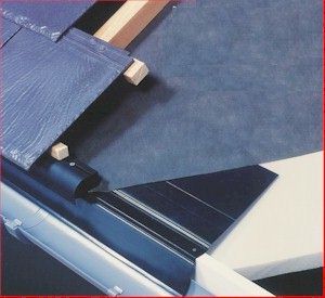
- What is more likely is rigid insulation board placed above the
rafters and counter battens fixed through it into the rafters below.
Because each timber rafter is below the insulation there are fewer
cold bridges and joints, making a thinner board more efficient.
At the ridge the insulation board needs to be mitred and sealed to
prevent a V shape cold bridge occurring. At the eaves the rigid
insulation needs to maintain continuity with the wall and will need
infill slabs to stand between the rafters to prevent a cold bridge at
the wall plate. With this arrangement any services, such as soil vent
pipes or roof windows that penetrate the rigid insulation will need to
be sealed to prevent a cold bridge.
|
|
Underlay |
| In many instances the rigid insulation manufacturers
recommend specific types of Vapour permeable underlay to ensure vapour
seeping through the joints in the boards is able to escape into the batten
cavity, and not condense on the underside of the underlay, and drain back
into the building.
The use of vapour permeable underlay to improve the thermal
performance of the roof will inevitably change the roof ventilation
requirements. If you do not have roof space ventilation below the underlay
then it will be needed above to ensure that there is a safe route for it
to escape into the outside air. To meet the ever more stringent
performance requirements, tiles are made to tighter tolerances (less gaps)
to allow them to be laid at lower rafter pitches. Less gaps means the risk
of water vapour condensing on the underside of the tiles and slates, or
worse still the timber battens, the greater the need for batten space
ventilation from eaves to ridge. Providing ventilation above the underlay
is best done with a 25mm over fascia vent at low level and a continuous
dry ventilated ridge system. If that is not possible, suitably spaced vent
tiles with shortened or no underside pipes.
|
|
The use of vapour permeable
underlays will allow the water vapour to pass into the batten cavity where
it will condense on the underside of the roof tile/slates. Without
ventilation at that point the battens and counter battens could be
affected in the long term.
|
|
|
Heating systems |
| The need for more efficient heating systems has seen the
number of Gas Condensing Boiler types increase. The act of extracting more
heat from the gas flame has resulted in lower flue gas temperatures. The
lower the flue gas temperature the greater the need for a fan flue system.
The cooler flue gasses, the higher content of water vapour and the higher
fan velocities have allowed the boiler manufacturers to reduce the
diameter of the flue and make them of plastic. |
| What has this to do with roofing? |
| Efficient building design requires the outer surface to be
reduced to a minimum, making terraced properties with room in the roof
more efficient. With less external wall surface, comes the compromise
between services and windows/doors. The answer is to locate the
gas-condensing boiler in the middle of the upper floor (airing cupboard)
and take the boiler flue directly up and out of the roof slope or ridge.
Some gas condensing boiler manufacturers are using standard inline vent
tiles, licensed for use as a gas condensing boiler terminal, rather than a
traditional flue pipe terminal. This may result in the choice of roof
covering being dictated by the heating boiler terminal specification,
rather than competitive price.
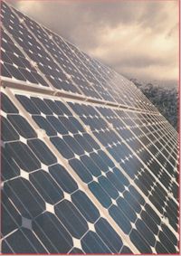
With the search for more efficient use of energy to heat
buildings and hot water, we will see more buildings with Solar Water
Heater or Photovoltaic panels that produce electricity, located on the
upper parts of south facing roof slopes. This is likely to result in more
systems being installed during construction or re roofing. At present the
systems available are not liked by planners as they are not visually
sympathetic to our traditional style of building, but some have been
designed to be integrated into the roof hiding all the brackets and pipes.
This trend combined with more compact housing units, may result in
complete roof slopes being nothing other than Solar Water Heater or
Photovoltaic panels.
|
| It will not be long before the
total south facing slope of most new roofs will be all solar panels. This
roof was designed and installed by Solar Century. |
|
|
Conclusion |
| Whilst at first sight the impact of Building Regulation
Approved Document Part L may not be very great on pitched roof coverings.
In the medium to long term there could be a significant effect on the
design and construction of roofs that will alter the specification and
construction of the roof. |