|
Reviewing or making a U-value calculation for an inverted flat roof? Then
you should bear these three vital considerations in mind . |
- U-values: Location, Location, Location.
- Design and declared lambda values: know
the difference.
- Roof build up and potential condensation
effects.
|
 |
| “We are all aware
of the importance of U-values when it comes to the long term energy
performance of well-constructed buildings. U-values can in general be
calculated easily, and there is software available to make such calculations
very quickly. |
|
Anything that makes the job easier is welcome –
but that doesn’t mean we should overlook vital factors which can lead to
misleading calculations if not addressed. With the spotlight turning on the
actual energy performance of buildings – not just the designed performance –
ensuring U-value calculations are robust is a responsibility the industry
must take seriously. |
| The
inverted flat roof is a building element with many unique aspects, which
must be tackled at the outset in order to avoid errors when making U-value
calculations. Water vapour movement as well as heat transfer should be
calculated, and in addition condensation issues need to be satisfactorily
addressed if a robust design solution is going to be achieved. Let’s take
each issue in turn. |
|
U-values: Location, Location, Location. |
| Most
people understand that two identical buildings, with identical U-values,
would not deliver equal energy efficiency performance if built in different
locations, due to differences in local climates. But you wouldn’t expect
this to affect a U-value calculation itself - or would you? |
|
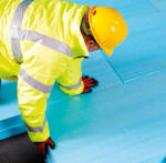
Inverted flat roof construction is simple in principle; just place the
insulation above the waterproofing layer rather than below it, as would
occur in traditional, warm roof construction. Interchanging the position of
the waterproofing and insulation layers brings numerous advantages, but also
introduces an additional mechanism for heat loss: rainwater can flow beneath
the insulation boards and remove heat directly from the building fabric,
before finally running off the roof and down the rainwater drainage outlet.
|
| This
effect is known as Rainwater Cooling, and it must be addressed when we do a
U-value calculation. So how do we do that? First, calculate the U-value
without taking it into account, and then add a correction (known as Delta U)
to obtain the final U-value. |
|
Obviously, the more rain which flows under the boards, the more heat is
lost. The additional heat loss due to Rainwater Cooling will therefore be
dependent upon the average rainfall in the building’s location and the
percentage of that rainfall which reaches the waterproofing layer. |
| BS EN
ISO 6946:2007 outlines a method which can be used to calculate how much the
U-value is affected by rainwater, and by how much we need to correct it. For
an edge-profiled, interlocking board, a substantial proportion of rainwater
can be expected to flow beneath the boards: European Technical Approval
Guideline (ETAG) 031-1 stipulates that 75% can be assumed for calculation
purposes. |
| This large
percentage can be reduced by placing a water control layer (not to be
confused with the waterproofing layer) over the insulation and beneath the
ballast layer. Tests have shown that this can reduce water flow beneath the
boards to typically around 5%, making a significant reduction to the Delta U
you would otherwise calculate. |
 |
| Whatever the
magnitude of the penalty that Rainwater Cooling brings, it needs to be
correctly taken into account when making U-value calculations for inverted
flat roofs. |
|
Design and declared lambda values: know the difference. |
| When
calculating U-values, we need to assess the individual materials which make
up the construction element and know their respective thermal resistances,
which can be derived from their thermal conductivity and thickness. If
proprietary materials are used, a manufacturer should be able to provide
relevant and - more importantly - accurate information for the calculation.
In other circumstances, it may be acceptable to use generic information for
the materials. |
|
Whatever the approach, there must be no confusion about the thermal
conductivity value to be used for the thermal insulation material, since the
overwhelming majority of the total thermal resistance which will contribute
to the final U-value is down to the thermal insulation layer. |
| All
insulation products have some degree of intrinsic variability in thermal
conductivity. European Products Standards therefore take thermal test
results and subject them to statistical analysis to create a level playing
field. This improves the robustness of thermal conductivities used in
calculations, and helps ensure that a consistent approach is used throughout
the entire process. It also takes mechanisms such as aging into account. |
| This analysis
delivers a so-called “declared” lambda value in accordance with the relevant
European norm for the insulation being considered. For extruded polystyrene
(XPS) such as STYROFOAM this norm is BS EN 13164. |
 |
| This declared
lambda value is sometimes referred to as the 90/90 value, i.e. 90% of
production achieves the quoted conductivity value with a 90% confidence
level. |
| Building designers
have come to accept that declared (90/90) values for thermal insulation can
be used as a design value as they represent a performance over a 25 year
lifespan. |
|
However in inverted flat roof applications this declared (90/90) value needs
to be additionally modified, by applying correction factors based on the
unique end use conditions. |
| ETAG
031-1 states that possible moisture absorption over time needs to be
determined by examining two particular mechanisms for water absorption: by
diffusion and by freeze/thaw, because the efficiency of thermal insulation
is impacted by the amount of moisture it contains. Only when the moisture
levels have been determined can the relevant correction factor be applied -
calculated in accordance with BS EN ISO 10456 - to the declared 90/90 lambda
value, in order to derive a relevant application design lambda value. |
| Adding
these correction factors will mean an increase in the thickness of
insulation required to achieve the same U-value. Ignoring them can lead to a
significant underestimate of the amount of insulation required to achieve a
target U-value. |
|
Roof build up and potential condensation effects. |
| The
optimum location for insulation is the outside of the building structure:
this minimizes thermal issues and helps to ensure that the dew point is on
the outside of the building. |
| The
possibility of interstitial condensation on an inverted flat roof is further
diminished, as the waterproofing layer is on the warm side of the insulation
boards and thereby acts as an efficient vapour control layer. Surface
condensation will also present a low risk, as the insulation boards maintain
the roof’s waterproofing close to the building’s internal temperature. |
| Nevertheless,
while condensation risks are low, they are not zero, and we need to consider
what other physical mechanisms may contribute. As already outlined,
rainwater is able to flow beneath the insulation boards, removing heat from
the roof structure. This results in a sudden drop in temperature and can
lead to condensation. |
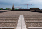 |
| For concrete decks
- which have a significantly large thermal inertia - the duration and extent
of deck cooling and therefore the consequent risk of either interstitial or
surface condensation can be considered minimal. |
| For
lightweight decks, however, rainwater cooling can pose significant risks
unless steps are taken to address it. |
|
Strictly speaking, the inverted flat roof concept involves placing all the
insulation above the waterproofing layer. However, designers from time to
time may be faced with design constraints, and they may want to consider
placing some insulation below the deck within the ceiling void. Care must be
taken with this approach, as increasing the thermal resistance below the
waterproofing layer only increases the risk of condensation forming. |
| This
increased risk cannot be offset by any ventilation of the insulation layer
inside the building, as this would effectively provide a thermal “short
circuit” and render the roof insulation ineffective altogether. |
| There
are no hard and fast rules as to how much thermal insulation can be
accommodated within a building before problems with condensation effects
emerge. However, it is generally recognized that for an inverted flat roof
design to perform effectively, the overwhelming majority of the insulation
must be placed outside of the building and above the waterproofing layer. |
| In
summary, yes, there is more than meets the eye when calculating U-values for
inverted flat roof systems and bearing issues such as condensation in mind.
However, guidance is available to help ensure we all get it right – and help
protect the reputation of the building industry as a whole.” |
|
For more information on Dow
Building Solutions see
www.roofinfo.co.uk/dow |
| |